How to make a self tuning mains Induction Heater

Please note for a high power IGBT version of this same coil please click here:
https://teslascience.wordpress.com/autotuning-9kw-induction-forge-version-1-2/
Today I am going to show you how to make a self tuning Induction Heater that can be plugged directly into the mains and should work with 110V AC or 220V AC. The one I will show you here is going to be tested at 110V AC. The idea for this project came from my interest in solid state tesla coils (SSTC). SSTCs are self resonating high voltage air core transformers that use a feedback loop which allows the circuit to operate at the resonant frequency of the secondary coil of the tesla coil to output large sparks. Richie Burnett and Steve Ward were the early pioneers of the SSTC design. See here
The circuit presented here is a modification of Steve Wards mini SSTC or better known as SSTC5 driver (https://www.stevehv.4hv.org/SSTC5.htm). The SSTC system stays in resonance because of a feedback loop either from an antenna which picks up electomagnetic field energy from the secondary coil or using a current transformer at the base of the secondary coil connected to the driver circuitry of the coil. The feedback signal is fed into a hex inverter or directly into the inputs of the MOSFET driver chips. MOSFETS are high power transistors that can handle high voltages and high currents making them ideal to make Tesla coils and induction heaters.
Before I go any further, just a word of warning. This project utilizes unprotected mains and generates high voltages, high alternating magnetic fields, and very high temperatures which can be dangerous resulting in injury which can be serous or fatal especially in untrained hands. Please regard the information in this page for academic purposes only. Now that I’m done with the obligatory blurb, lets get on with it!
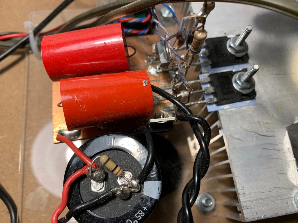
Modern induction heaters are solid state devices that take the AC electricity either from the mains or from an autotransformer or switching power supply and rectify the voltage to DC which is smoothed with a smoothing capacitor. The heater described here can be plugged directly into 120V AC mains as there is a a 250 V 30A anatherm thermister (see Figure 2) which prevents a current spike on the full bridge rectifier when the electrolytic capacitor charges up. The rectified mains is fed into a half bridge (or full bridge) inverter. The half bridge inverter is basically a 2 poled switch consisting of two MOSFETs ( see Figure 2 )
Figure2:

which will allow current to flow to a load (in this case a 22 turn coupling transformer) which is an impedance matched transformer with a series LC arrangement of the work coil and capacitor bank. This “series” topology is hard on the MOSFET based switch which has to pass all of the current drawn by the load as well as reactive current. The current flows in a too and fro motion so that the direction of the current in the coupling transformer continually switches direction as the 2 MOSFETS of the half bridge inverter are alternatively switched on and off. The signal to the gate of the MOSFETs is isolated from the low voltage driver circuitry by using a gate drive transformer or GDT. Protection diodes are placed on the gates of the MOSFETs. The 6.8 Ohm resistor on the gates prevents “ringing” on the gates as the gate capacitance and the turns on the GDT transformer creat an LC circuit capable of high frequency ringing which can have undesirable effects on switching. The GDT simultaneously affords galvanic isolation of the delicate low voltage circuitry and the high voltage high currents in the MOSFETs. We need to drive these MOSFET switches at the resonant frequency of the series LC tank circuit. This is achieved by a feedback loop achieved passing one of the limbs of the workcoil or heating coil of the LC series tank circuit through a small ferrite transformer wound with 100 turns of thin wire and connected accross an approximately 20 Ohm power resistor.
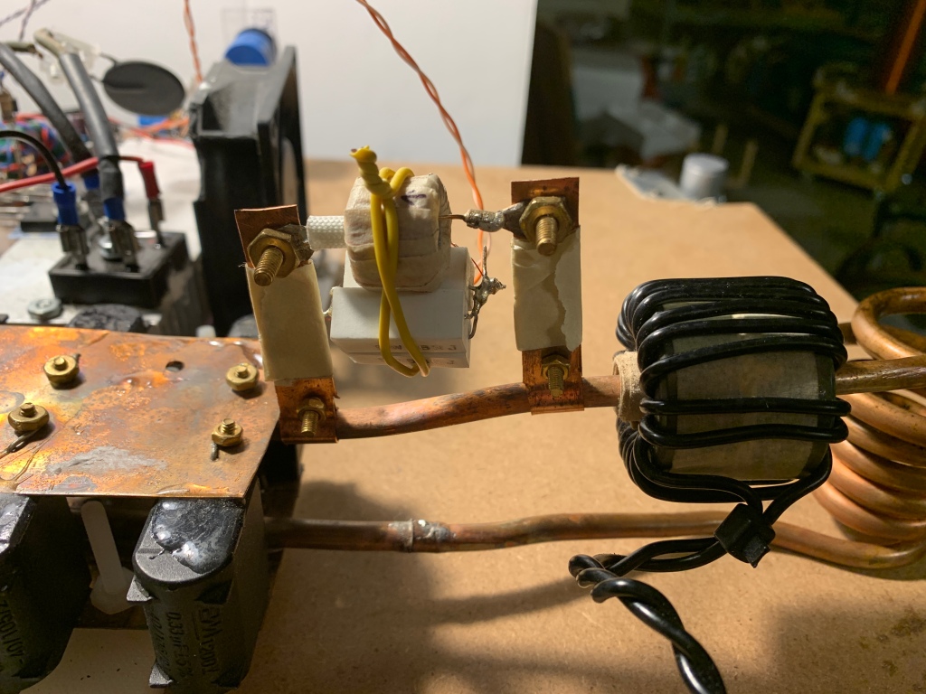
So for example, if there is 500A of current flowing in the primary tank, with a 100 turn current transformer and 20 Ohm burden resistor, this will be reduced by the current transformer 100 fold to 5A. V=IR which means V=5 x 20 = 100V. The 100V output of this current transformer is a sine wave.
Figure 1:
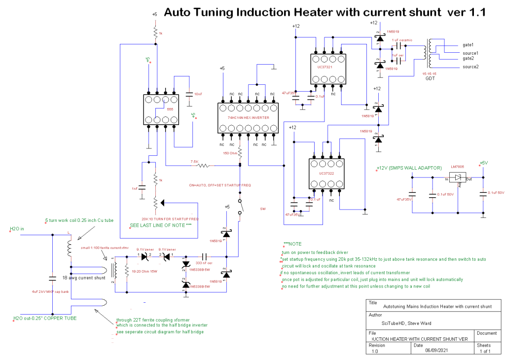
This 100V output is too high for the delicate feedback driver circuit (Fig 1), so the voltage across the burden resistor has to be reduced. This is done by putting a thin piece of wire in parallel with one of the limbs of the workcoil. In our case we are using 18 gauge wire. The cross sectional area of the copper in the 0.25 inch copper tubing is 21mm2. The cross sectional area of 18 gauge shunt wire is 1mm2. The shunt therefore reduces the current from 500A to 500/21=24A. In the 100 turn current transformer, this is reduced to 24/100=0.24A. V=IR. With a 20 Ohm burden resistor, V=20 x 0.24=5V. As typical currents are greater then 500A typically more then 1000A in the work coil, between 10-20V is the voltage generated from the current transformer which is better for the feedback circuit. This 10-20V has to be clamped to 5V which is the acceptable TTL input voltage for the hex inverter. Clamping is achieved with a series of zeners (see Figure 1).
To obtain startup oscillations in the right range, a 555 timer chip configured for astable oscillator operation with variable frequency adjustable with a 10 turn 20k potentiometer is utilized (Figure 1). The 555 can be powered from 5 to 12V. We are using 5V for convenience since this is the maximum operating voltage of the hex inverter. The 555 generates a square wave signal. The pot is tuned to produce a frequency identical to or just slightly above the resonant frequency of the series tank circuit (see later how to do this). The 5V square wave output of pin 3 of the 555 is weakened by passing it through a 7.5 k resistor before it is sent to one of the input pins of the 74HC14 hex inverter. At the input pin of the hex inverter, this weakened signal looks more like a blunted sine wave then a square wave. Because of this, the inverted output of the hex inverter looks more rectangular then square because the input is sine and the hex only sees the top portion of the 5V sine wave input. Because of this clipped sine wave, the duty cycle of the output from the hex is therefore less then 50%. This is passed to the input pin 2 of the UCC37321 and UCC37322 inverting and non inverting gate driver chips. The enable pin 3 of the UCC chips is not connected (default state is enabled). This UCC chip pair therefore outputs a less then 50% duty cycle signal which is fed into a 15:15:15 medium sized GDT wound using CAT5 or just regular trifilar hookup wire. The output of the GDT should be as square or rectangular as possible. This is achieved using the correct number of turns (typically 10-20) on the ferrite core, right size of core (typically 1.5-2 inch diam), and the right type of ferrite material. Getting the right output waveform is empiric and requires an oscilloscope. An excellent description of correct output from a gate drive transformer is presented here by Richie Burnett. The trifilar winding on the GDT has to be such that the outputs are inverting and non inverting, ie the output of one of the 2 secondaries on the GDT is reversed so that when one MOSFET of the half bridge is switched on the other is switched off otherwise they would both be on at the same time creating a short circuit.
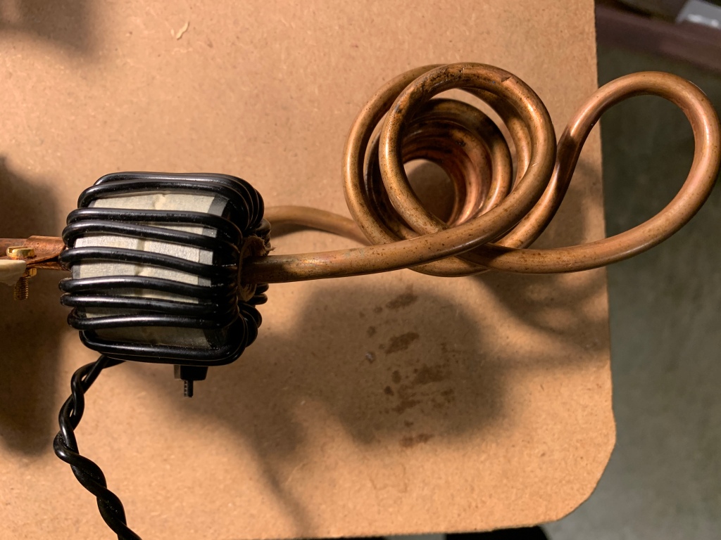
3.3 uF polypropylene (PPE) film capacitors placed between the output of the MOSFETs and the load in this case the coupling transformer act as DC blocking capacitors. The alternating output of the half bridge feeds into the 22 turn ferrite coupling transformer (See Figure 1 and 2) which in turn generates an alternating magnetic field. Design of the impedance matched coupling toroidal transformer ie number of turns, size, and type of ferrite material has to be experimented with for best results. Typically around 20-22 turns and ferrite works best but there are also different types of ferrite. The ferrite cores can be stacked. In this case I used a stack of 2 smaller ferrite toroids taped together to form a bigger one. When this coupling transformer is inductively coupled with the LC tank circuit by passing a limb of the series LC tank through the center of the donut of the coupling transformer (see Figure 3), alternating current begins to flow in the tank. At resonance, there is build up of voltage and current in the tank to high levels.
Figure 3:
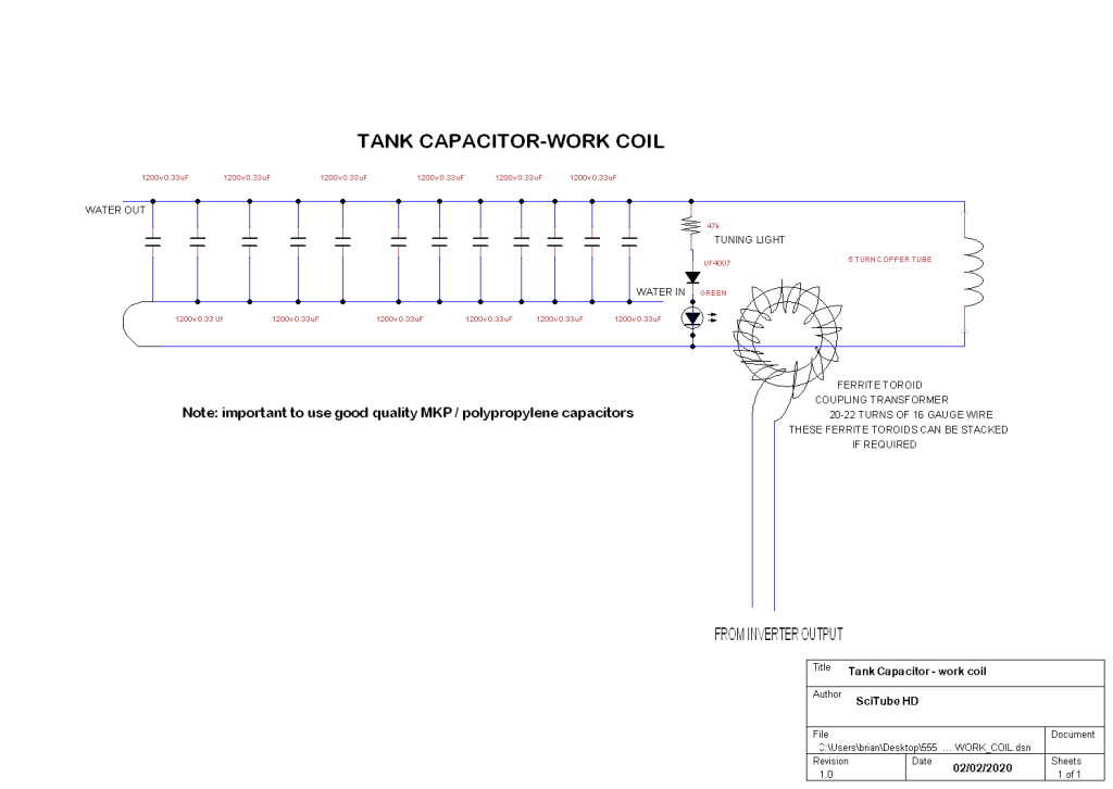
The “tank” which is a series resonant circuit consists of a capacitor bank and inductor (work coil) connected in series. When these are at resonance, their combined impedance approaches zero which allows very high currents to be pushed through the work coil of the order of 1000s of amps.
In this case, our series tank capacitor bank consistsd of 12 x 0.33 uF 1200V polypropylene film capacitors designed for use in induction heaters/cooktops and connected together in parallel (total 4uF) (see Figure 3). The work coil is 5 turns of 0.25 inch soft copper tube 3.5 cm outer diameter made by filling the copper tube with fine table salt, sealing off both ends, and then wrapping the tube around a thin piece of PVC pipe that has been secured firmly. The salt or sand is necessary to prevent the tube from kinking when the coil is wound (the sand or salt is blown or tapped out of the coil once the desired size and shape is obtained). For inductive levitation experiments, a more conical coil configuration is necessary with the top winding of the coil wound in the opposite direction to allow stable inductive levitation of metals:

The capacitors are connected together using thin copper sheet:

The capacitor leads can be soldered or bolted to the copper sheet using brass bolts. Iron would heat up. The copper pipe is soldered onto the copper sheet with a blowtorch, plummers solder, and plenty of flux for best electrical connectivity.
Cold water is passed through the copper tubing since the tubing gets hot during operation. The flow of water is maintained with a 12V fountain pump connected to a wall adaptor.
Both MOSFETs of the half bridge inverter are heatsinked to a fan cooled heatsink and electrically isolated from one another using silicone thermal heat pads. Mica heat pads allow even better heat transfer. The output of the half bridge inverter is connected to the toroidal ferrite coupling transformer (22 turns 16 gauge wire in this case) which is 22:1 coupled to the series tank by simply passing the copper tubing of the tank through the toroidal transformer:
The series tank is therefore galvanically isolated from the half bridge circuit. The startup frequency is obtained by first setting the switch (Figure 1) to manual tune and then using a small variac adjusted to 40-70V AC. The frequency of the pot is adjusted identical to or slightly above resonance (LED on tank will be on and bright) and then no further adjustment of the startup frequency is needed for the particular work coil that is employed. Once the right frequency is obtained on the pot, disconnect the variac and set the switch to “auto”and plug directly into 120V mains. Feedback will automatically take over from now on and the unit becomes essentially plug and play.
At this point let’s discuss the feedback mechanism. At resonance with 110-125V AC input, thousands of amps are flowing in the tank circuit. It is this high alternating current in the tank that can cause contact-less heating of metals. The metallic work piece in the work coil acts like a shorted one turn secondary coil and due to the massive currents which are further increased by the step down ratio (workpiece acts like a shorted one turn secondary coil) gets hot through resistive losses that become apparent at these high current levels. In addition to the resistive losses, ferromagnetic metals such as iron or steel also undergo heating due to hysteresis effects. The iron metal contains randomly arranged magnetic dipoles which when placed in the massive alternating magnetic fields in the coil move with the alternating magnetic field and produce additional heat due to friction.
In this setup the feedback current transformer (see above) is wound with 100 turns thin wire (30 gauge copper magnet wire). This current transformer uses ferrite for the core material as iron would get hot very quickly!
Output of this transformer is fed into 2 opposing 9.1V 1W zeners and into the the input pin (the same one that the 555 output connects to) of the hex inverter via a 150 Ohm resistor. The input signal is further clamped to 5V with a series of zeners. Because of the 9.1V zeners, there will be no feedback until the output of the current transformer exceeds 9V (see below for why we need the opposing 9.1V zeners).
As the input voltage on the half bridge is increased further, the low signal from the 555 is overridden by the signal from the feedback transformer. If the 9.1 V opposing zeners pair is absent, then the low signal from the 555 is shorted through the feedback transformer and there would be no startup oscillations because the input pin 3 of the hex inverter does not see any of the 555 signal. So the 9.1V zener pair is absolutely necessary. Once the signal from the 555 is overriden from the feedback transformer, the system resonates spontaneously and no longer requires the presence of the 555. At resonance, the duty cycle as seen from scoping the gate signal on the MOSFETs increases to 50%.
The main advantage of this system is it just drops into resonance as the power level goes up! With 120V mains input the power consumption is >1kW. For more power, larger MOSFETs or a full bridge setup would be in order.
Half bridge with DC blocking metal film capacitors:
This is the ferrite toroid (green one) I used for the gate drive transformer wound with 15 turns trifilar hookup wire. Next to it is the driver circuitry with 555, hex inverter, and mosfet driver chips which connect to the primary windings of the gate drive transformer:

For a quick video demo of the coil operating at 120V AC, check this video:
Here is a demo of the coil being used to levitate and ignite a piece of potassium metal while it is suspended in mid air:
I hope you find this page useful to build an easy to use mains powered induction heater based on the awesome Tesla Coil work put forward by famous coiler Steve Ward. Any ideas of suggestions on how to change this circuit to make it current limiting would be welcome. If anyone would like to collaborate on this project idea, please contact me.
